
Written by "Jeepineer" our co-founder and chief engineer, and the inventor of the 6Pak shock and Duroflex joint, the following was used to help us all understand coil rates better and why Metalcloak uses TRUE Dual Rate Coils.
Enjoy.
Enter "Jeepineer"...
Understanding Suspension Springs & their Design (and why we use Dual Rate) - A white Paper on Coils...
I am going to provide specific values for spring rate, load at ride height etc. for discussion purposes only. These are not actual numbers because most manufacturers have proprietary spring rates and loads that they believe are ideal for a quality ride or are tuned for their specific systems (so does MC). All numbers are examples only.
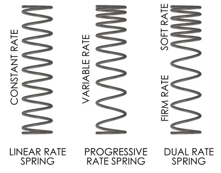
Linear Rate Springs...
Stock springs are linear rate springs. Many of the larger suspension manufacturers use Linear Rate Springs. Linear springs cost less, are simpler to design, simpler to inspect and provide fairly consistent ride heights.
Unfortunately they are not good for long travel suspensions for the following reason. I will use an example to explain.
Assume the front driver side spring of a JK has to hold a load of 600lbs at ride height.
Assume the spring must compress to a length of 10” at ride height for a given lifted JK. (Lift height does not matter for this discussion)
Assume our example is a lifted average travel suspension system and the Free Length (fully extended length) of the Spring is 14”
The spring rate of this spring is equal to the Load at Ride Height (600lbs) divided by the Length the Spring must compress (4”).
Actual Calculation
600lbs / (14” - 10”) = 150lbs/in
Let’s assume that 150lbs/in is the perfect spring rate for the perfect ride quality of a JK. Not too squishy (move all over the place) not too stiff (feel every little bump on the road).
Now, let’s look at what happens when we need a spring that will remain seated in a long travel suspension at the same lift height.
So let’s assume that we need the Free Length (fully extended length) of our example spring for this long travel suspension to be 18”.
The 10” compressed length of the spring at the same lifted ride height remains the same.
Again The new spring rate is equal to the Load at Ride Height (600lbs) divided by the length the spring must compress (8”) .
New Calculation
600lbs / (18” - 10”) = 75lbs/in
The new example spring rate of 75lbs/in will feel too soft to driver of the vehicle. The vehicle will role or bounce at the slightest motion.
This is the problem with Linear Rate Springs when you want to make a longer travel suspension that requires longer free length springs....the spring rate just gets too low by the time the spring compresses to the desired lifted ride height.
In other words, if we want to maintain the example perfect ride quality of 150lbs/in in a long travel suspension it becomes impossible with a Linear Rate Spring.
Therefore long travel suspension companies that want their springs to remain seated throughout the travel of the suspension and provide a ride quality at least in the same realm as the stock vehicle they must use a spring other than a Linear Rate Spring.
Two solutions are Progressive Springs and Dual Rate Springs. We will describe those next.
Progressive Rate Springs...
This post will discuss Progressive Rate Springs (in marketing jargon also referred to as Triple Rate or Quad Rate). I am going to provide specific values for spring rate, load at ride height etc. for discussion purposes only. These are not actual numbers because most manufacturers have proprietary spring rates and loads that they believe are ideal for a quality ride or are tuned for their specific systems (so does MC). All numbers are examples only.
Progressive Rate Springs- Many top end long travel suspension manufacturers use Progressive Rate Springs. There are two ways to produce a progressive rate spring.
1) Continuously Variable Rate (Pitch)....or the winding of the spring coils such that the distance between each subsequent active coil (coil pitch) of the spring increases as you progress from the top coil to the bottom coil. In other words, the coil pitch continouosly changes throughout the entire length of the spring. Production of this type of progressive rate spring is rare as it requires specialized CNC spring winding machines.
2) Combining 3 or more Spring Rates (Pitches)....most Progressive rate springs are produced using a combination of 3 or more linear spring rates (coil pitches) wound into a single spring coil. Some manufacturers use marketing terms like Triple Rate or Quad Rate springs, however these are really just progressive rate springs with a fancy name. Let me explain what I mean...when one uses three spring rates (coil pitches) in a single spring, each spring rate must also have a transition rate (coil pitch) between each of the three spring rates, therefore a spring with three spring rates must effectively have a total of 5 spring rates. Once you have that many different spring rates in a single spring coil it is effectively an estimate of a progressive rate spring. In other words, Progressive Rate Springs, Triple Rate Springs, Quad Rate Springs are all the same thing with just different names. I will refer to all of these as Progressive Rate Springs in this post.
Progressive Rate springs are generally more expensive to make, harder to design, harder to inspect and do not have the ride height consistency of linear rate springs. They are excellent springs for long travel suspension systems. Look at the Progressive Spring in the image above. Notice that the distance between the active coils (Pitch) steadily increases as you progress from the top coil to the bottom coil. This is how you can identify a true progressive spring from a marketing progressive spring.
A true Progressive Rate Spring is progressive by RATE. Meaning the spring rate increases the further the spring is compressed.
Unfortunately a Linear Rate Spring is progressive by FORCE. Meaning the load force of the spring increases the further the spring is compressed. I have seen some manufacturers claim there springs are progressive and technically they are progressive by force but not by rate.
Notice how the last two active coils are the furthest apart (I will return to this later in the post).
So I am going to use the same spring assumptions I used in the last long travel suspension example:
Assume the desired spring rate for the perfect ride is again 150lbs/in
Assume the compressed length for the Progressive Spring at ride height is again 10”
Assume that the Free Length for the Progressive Spring is again 18”
So in summary we need our spring to compress a total of 8” (18” - 10”). When it compresses this 8” and reaches the desired length of 10” it needs to handle a load of 600lbs and have a rate of 150lbs/in at that specific point.
The following is a chart of what is happening with the progressive spring as we compress it to the desire ride height. I hope this chart works on your screen.
Spring Compression___Spring Rate at Compression__Force at Compression___Length of Spring
___0_________________________0____________________ _0_________________18”
___2”_____________________20 lbs/in________________40 lbs______________16”
___4”_____________________40 lbs/in________________120 lbs_____________14”
___6”_____________________90 lbs/in________________300 lbs_____________12”
___8”____________________150 lbs/in________________600 lbs_____________10”
So this is an example of a progressive spring with a continually changing rate that will work in the example long travel suspension used above.
As you can see the Spring Rate is changing as the spring is compressed and aproaches the desired ride height. This is what makes it more difficult to provide a consistent ride height because the Rate and the Force of the spring are both changing at the point that the user wants his/her ride height. Remember I said it makes it more difficult not impossible.
In addition, as the Progressive Spring in the image above, compresses every coil of the spring will move the same distance resulting in the top coils slowly collapsing on top of one another before the lower coils collapse on one another. As a coil collapses on a previous coil it becomes fully supported or solid and no longer acts as an active part of the spring at all. This collapsing of coils onto one another is the exact mechanical feature that causes a Progressive Rate Spring to act as a Progressive Rate Spring.
In other words, as spring coils are removed from being active the fewer remaining active coils result in the spring becoming stiffer. It is the same concept as a long rod being easier to bend (softer) than a shorter rod of the same diameter (stiffer).
This is another way to identify if you truly have a progressive rate spring or not. If the coils of your springs do not progressively stack directly on top of one another (touching) during a good portion of the compression cycle of the spring you likely do not have true progressive rate springs. Or your spring has not reached its progressive rate stage within the compression cycle that you viewed.
Progressive Rate Springs have a very nice feature in that they substantially increase in rate as you compress beyond ride height. This helps to reduce the force of impact of the axles on the bump stops under extreme off road conditions. Nice feature over linear springs.
Now for the number one reason MC did not choose to design our springs as Progressive Rate Springs.
We use a lot of up travel in our suspension systems therefore our springs get very close to the fully compressed (all coils touching) condition. Progressive Rate Springs do not like to be fully compressed as they are susceptible to sagging. If you can picture an almost fully compressed Progressive Rate Spring, all of the top coils will be collapsed on one another and inactive while only the very last active coil will be active. In this condition the largest amount of spring stress is concentrated in the final active coil. Substantially more stress than what is in the first coil that collapsed and became solid long before the fully compressed condition. This large concentration of stress in a single coil can cause the spring to fatigue and sag over time.
Therefore MC chose to use Dual Rate Springs.
Dual Rate Springs (used in MC suspensions)...
The diagram above shows three types of springs commonly used in the offroad industry. This post will discuss Dual Rate Springs specifically shown in action in the diagrams below. I am going to provide specific values for spring rate, load at ride height etc. for discussion purposes only. These are not actual numbers because most manufacturers have proprietary spring rates and loads that they believe are ideal for a quality ride or are tuned for their specific systems (so does MC). All numbers are examples only.
Dual Rate Springs – are just another type of progressive rate spring, however a Dual Rate Spring’s progression is from a first rate (Flex Rate) to a second rate (Ride or Road Rate) as opposed to the continually changing rate of a traditional progressive rate spring. I think very few long travel suspension manufacturers use Dual Rate Springs. Dual Rate Springs are generally more expensive to make, harder to design, and harder to inspect than linear rate springs. But Dual Rate Springs do have the similar ride height consistency of linear rate springs. Dual Rate Springs are excellent springs for long travel suspension systems.
Look at the Dual Rate Spring in the image above. Notice that the distance between the top approximateLY 4 active coils (Pitch) is smaller and identical to one another. Notice that the distance between the bottom approximately 4 active coils (Pitch) is larger and identical to one another. This is how you can identify a true Dual Rate Spring.
Because of the unique appearance of a Dual Rate Spring it is easily identifiable from a Linear Rate Spring. In other words it would be very difficult to market it as anything but a Dual Rate Spring.
Using the same spring assumptions from the previous two posts for the same example long travel suspension:
Assume the desired spring rate for the perfect ride is again 150lbs/in
Assume the compressed length for the Dual Rate Spring at ride height is again 10”
Assume that the Free Length required for the Dual Rate Spring is again 18”
So in summary we need our spring to compress a total of 8” (18” - 10”). When it compresses this 8” and reaches the desired length of 10” it needs to handle a load of 600lbs and have a rate of 150lbs/in at that specific point.
The following is a chart of what is happening with a Dual Rate Spring as it is compressed to the desired ride height.
Spring Compression___Spring Rate at Compression__Force at Compression___Length of Spring
___0_________________________0____________________ 0________________18”
___2”_____________________25 lbs/in________________50 lbs______________16”
___4”_____________________25 lbs/in________________100 lbs_____________14”
___6”_____________________25 lbs/in________________150 lbs_____________12”
___7”____________________150 lbs/in________________300 lbs_____________11”
___8”____________________150 lbs/in________________600 lbs_____________10”
So this example of a Dual Rate Spring meets the goals for the design of the example long travel suspension. In this case the transition from Flex Rate (1) to Road (Ride) Rate (2) occurs at about 7” of compression or 1” above the desired ride height.
Note that the Spring Rate is not changing as the spring compression approaches the desired ride height, only the force is changing. That makes it much easier for the manufacturer to maintain consistent ride height. I am not knocking progressive rate springs or saying they do not maintain consistent ride heights I am only saying it is more difficult to do so with progressive rate springs.
The fact that the bottom 8 active coils remain active throughout the full compression cycle of the spring is the main reason we chose Dual Rate Springs for the MC suspension. As stated in the previous Progressive Rate Spring Post. MC uses a lot of up travel in our suspension systems therefore our springs get very close to the fully compressed (all coils touching) condition. But even when our suspension is close to this fully compressed condition the stress in the spring is distributed equally across all of the 8 bottom active coils. In other words, we spread the heavy lifting out to multiple coils. This feature of Dual Rate Springs helps to prevent spring fatigue and sagging which MC believes is a major concern of customers.
Properly designed Dual Rate Springs and some Progressive Rate Springs (depending on design) have a unique feature that results in added spring stability and therefore added suspension stability. MC calls this feature “dropping the virtual spring bucket”. This feature is illustrated in the image above.
In order to discuss we have to agree on the following assumption.
If one compares a LONGER spring to a SHORTER spring both having the same wire diameter, same number of coils and same spring diameter, the LONGER spring is more likely to buckle and demonstrate lateral instability than the SHORTER spring.
As you can see in the image above when the Flex Rate Coils collapse they become solid and fully supported by one another. In effect…it is like the spring bucket that is retaining the top of the spring moves down to a new location or “virtual spring bucket”. This in turn results in the spring effectively becoming SHORTER and therefore more stable and less likely to buckle.
I hope this information is helpful.